Project Description
The objective of analysis was to check stress levels in the Nozzles on condenser (N1, N2, N3, N4, N5, N6, N7, N8, N32, N33 and N34). Condenser is designed as per ASME Section VIII, Div. 1 Ed. 2017, TEMA R AXS, API 650 and FEA analysis of nozzle is carried out as per ASME Section VIII, Div.2, Part 5. To investigate the stress levels in nozzles linear static finite element analysis is carried out. 3D CAD model generated for analysis is as per geometric details provided, names of drawings are mentioned in chapter 6. The Finite Element Analysis is carried out in ANSYS Workbench.
Design Code: ASME Sec VIII Div. I, Ed. 2017, TEMA R AXS, API 650
| Shell Side | Tube Side | |
|---|---|---|
| Design Temperature (°C) | 18/200 | 18/121 |
| Design Pressure (Max./ Min.) (kg/cm2 g) | 3.5/F.V. | 13/F. V |
| Corrosion Allowance (mm) | 6.0 | None |
Material of Construction
| Components | Material Grade |
|---|---|
| Shell side shell, Nozzle RF pad N3, N4, N5 | SA 516 Gr. 70 |
| Nozzle neck N3, N4, N5, Nozzle Neck N6, N7, N8, Nozzle N29 -N31, Nozzle Neck N32-N34, | SA 106 B |
| Boot Head | SA 234 WPB |
| Channel Shell, Nozzle N1, N2 RF pad | SB 171 C70600 |
| Nozzle Neck N1, N2 | SB 466 C70600 |
Material Properties for Analysis
| Material | Design Temperature(°C) | Elastic Modulus (MPa) | Allowable Stress(MPa) | Yield Strength (MPa) | Density (Kg/m3) | Poisson’s Ratio |
|---|---|---|---|---|---|---|
| SA 516 Gr. 70 | 200 | 192.0E03 | 138.0 | 225.0 | 7750.0 | 0.30 |
| SA 106 B | 200 | 192.0E03 | 118.0 | 207.0 | 7750.0 | 0.30 |
| SA234 WPB | 200 | 192.0E03 | 118.0 | 207.0 | 7750.0 | 0.30 |
| SB 171 C70600 | 121 | 120.16E03 | 64.1 | 95.8 | 8940.0 | 0.33 |
| SB 466 C70600 | 120.16E03 | 55.1 | 82.5 | 8940.0 | 0.33 |
Methodology
The study is conducted to determine the stress level in Nozzles N1, N2, N3, N4, N5, N6, N7, N8, N32, N33, N34 on condenser. The study is conducted using the following methodology:
- 3D CAD model of Nozzle is generated with the help of drawings provided. 3D Model includes part of shell, channel, Nozzles, saddle support, shell flange, channel flange. 3D model is divided in to two models as per nozzles locations i.e. shell side nozzles & channel side nozzles. Drawing used for FEA analysis are mentioned in chapter 6.
- FEA Analysis is carried out for the following load cases:
- Shell Side Nozzle Analysis Load cases –
- Load Case 1 – Internal Design Pressure + Nozzle thrust + Nozzle Process Loads (shell side nozzles)
- Load Case 2 – External Design Pressure + Nozzle thrust + Nozzle Process Loads (shell side nozzles)
- Channel Side Nozzle Analysis Load cases –
- Load Case 3 – Internal Design Pressure + Nozzle thrust + Nozzle Process Loads (channel Side Nozzles)
- Load Case 4 – External Design Pressure + Nozzle thrust + Nozzle Process Loads (Channel Side Nozzles)
- FEA Analysis Results are validated as per ASME Sec. VIII, Division 2, Part 5 Edition 2019.
- Results are studied and presented in the following sections.
- FEA Analysis is carried out in Ansys Workbench software.
Detailed procedure is presented in following pages with aid of supporting graphics.
Geometry Parameters
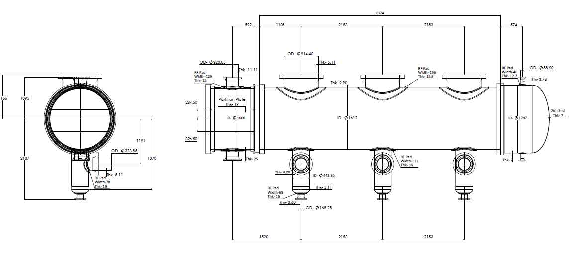
3D CAD model (Corroded Geometry)
Geometry– 3D CAD model
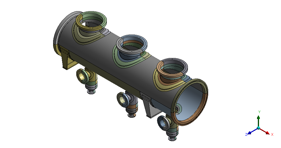
3D CAD model – Shell Side Nozzles
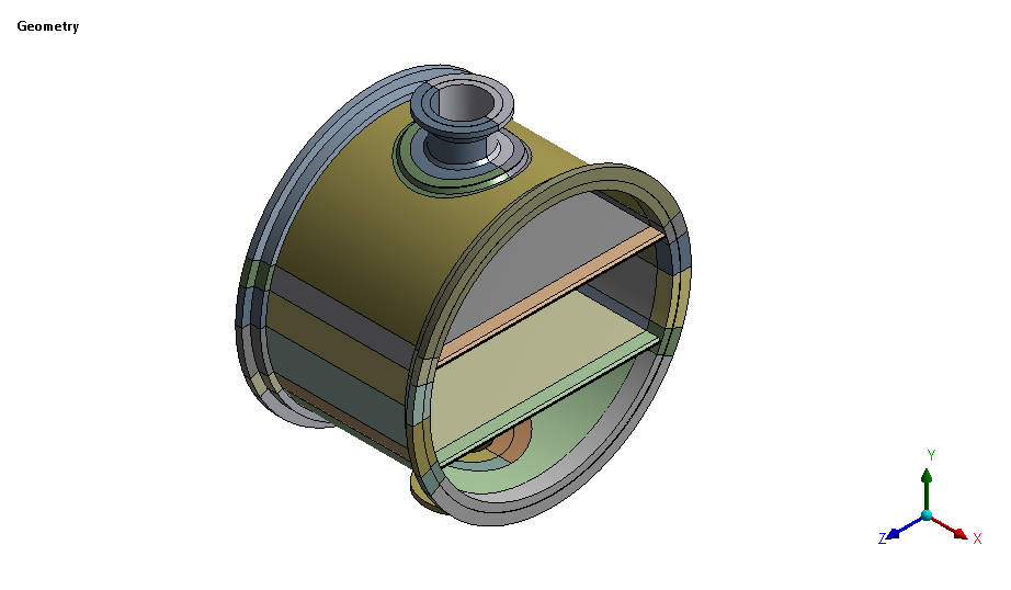
3D CAD model – Channel Side Nozzles
Finite Element Model:
Finite Element Model is based on 3D CAD model of Nozzle N2
Solid-186 elements are used for analysis for Nozzle N2
- Total numbers of Elements in Model = 248560
- Total numbers of Nodes in Model = 818379
Overall mesh quality checks with their acceptable limits and achieved values are shown below in Table 2.1
| Quality Check | Acceptable Value | Achieved Valve |
|---|---|---|
| Aspect Ratio | < 5 | 2.69 |
| Jacobian Ratio | > 0.5 | 1.69 |
| Skewness | < 0.70 | 0.33 |
| Element Quality | > 0.1 | 0.69 |
FEA Analysis for Nozzles (Load Case – Internal Design Pressure + Nozzle Thrust + Nozzle Process Loads (Shell Side nozzles) )
Structural loading condition
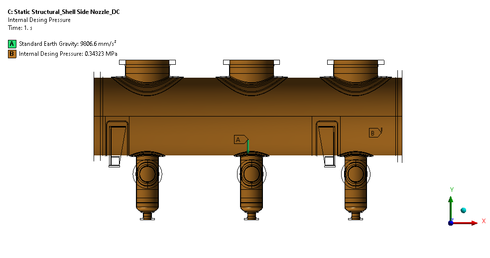
- Self-weight of model is applied as a gravity load in downward direction as shown in figure 3.1.1
- Internal design pressure of 5 kg/cm2g (0.3432 MPa) is applied on internal faces of shell, shell side nozzle as shown in figure 3.1.1
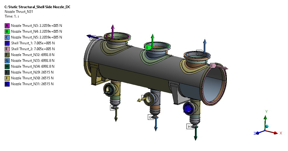
- Thrusts due to internal pressure is applied on nozzle flange face as shown in figure 3.1.2, Thrust calculations are given in table 3.1
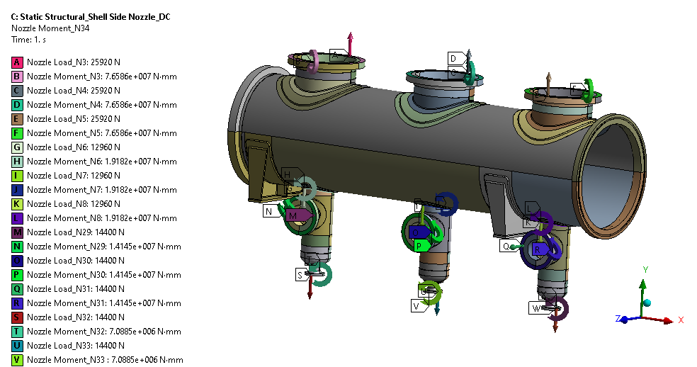
- Nozzle Process loads is applied at nozzle flange face as shown in figure 3.1.3
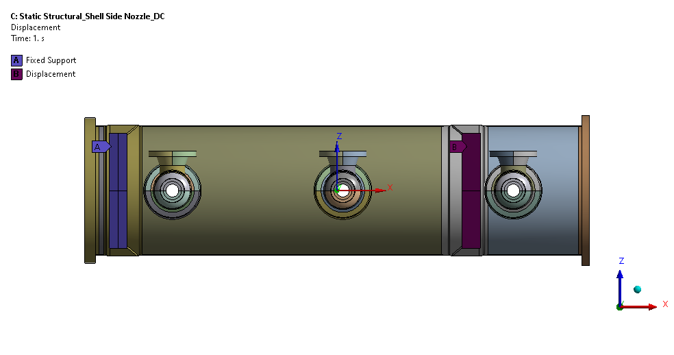
- Fixed boundary condition is applied at bottom face of fixed saddle support while displacement support is applied at sliding saddle support as shown in figure 3.1.4